
How to Choose Soldering Tips for Automatic Soldering Machines & Robots
On a manual soldering station, an experienced operator constantly compensates — a slight wrist angle, a fraction more dwell time, a tiny push. An automatic soldering machine cannot do that. It repeats exactly the same path, angle, and dwell cycle, thousands of times an hour.
That is why tip selection on an automated line is unforgiving. The right automatic soldering tip delivers stable wetting, tight cycle times, and long service intervals. The wrong one produces cold joints, solder bridges, and unplanned line stops — even when every machine setting is correct.
This guide walks engineering and procurement teams through the five decisions that matter: machine compatibility, tip geometry, thermal mass, iron plating, and real tip cost.
1. Start With the Machine, Not the Tip
Before comparing shapes or prices, identify the heater cartridge and tip holder on your equipment. The machine determines which tip families physically fit — a tip that looks identical but has a slightly different seating length or heater bore will not transfer heat correctly and may damage the cartridge.
| Automatic equipment | Compatible tip family |
|---|---|
| Apollo Seiko robots | PAD series |
| UNIX robots | P2D / P3D series |
| TSUTSUMI robots | TKH series |
| 911-type and 4–5 axis desktop robots | 911 / 911G, XT and XJ series |
| JBC automated soldering units | C245 / C470 cartridges |
Power matters too. Machines rated 80–150 W are typically used for fine-pitch and small SMD work, while 200–400 W+ systems are built for heavy thermal loads and drag soldering. A heavy tip on an underpowered heater never reaches a stable working temperature; a micro tip on a high-power unit overshoots and burns out quickly.
Always confirm the exact model on the machine nameplate and cross-check the part numbers of tips currently in use before ordering. For a brand-by-brand compatibility reference, see our guide to compatible tips for JBC, Hakko, Weller and Apollo Seiko stations.
2. Match Tip Geometry to the Joint
This is the decision that most directly affects joint quality. On a robot, contact angle and working surface are locked in at programming — the tip geometry must suit the joint from the very first cycle.
| Joint / application | Recommended geometry | Why it works |
|---|---|---|
| Single pad, small SMD, fine-pitch component | PC (pad) type, flat end face | Even contact on one pad, no neighboring pad disturbance |
| Multi-pin connectors and pin headers (drag soldering) | DV V-groove (DV1 / DV2) | Groove channels solder along a row of leads in one pass |
| Large pads, thick leads, terminals and coils | Wide chisel (D type), high thermal mass | Stores enough heat to wet heavy joints without temperature collapse |
| Deep cavities, back-side joints, crowded boards | Bent tips, 45° / 90° custom angles | Reaches joints a straight shaft cannot access without interference |
| Through-hole pins and wire terminations | Flow / grooved contact surface | Controlled solder feed and consistent fillet shape |
For drag soldering connectors, the groove profile is what makes automation practical: instead of soldering 20 pins individually, the robot draws the tip once along the row, and the V-groove deposits an equal amount of solder on every lead. Our 911G DV1 V-groove handles single-row drag soldering, while the 911G DV2 double V-groove is used for two-row connectors and higher-throughput passes.
When a board has components shielding the joint or requires soldering from the side, no amount of reprogramming replaces a correctly bent shaft — see the C470 bent-tip engineering case for how geometry solved an interference problem.
3. Size the Thermal Mass Correctly
A soldering joint receives energy from the tip’s working surface. On an automated line with cycle times of just a few seconds, the tip must recover its temperature between joints. A tip that is too small for the joint loses heat faster than the heater can replace it; a tip that is too large for the pad floods neighboring joints and lifts pads or melts plastic housings.
The three most common mismatches we diagnose:
- Tip too small for a heavy joint — coils, metal brackets, connector shells and ground-plane pads pull heat away instantly, causing cold joints and peaked solder.
- Tip too large for fine pitch — excess contact area creates bridges and damages adjacent components.
- Compensating with higher temperature — raising the set temperature to force wetting is the standard workaround, and the worst one: every 50°C increase roughly halves tip plating life.
The correct approach is to use the largest end face that wets the target joint within 2–3 seconds, at the lowest effective temperature — typically 320–360°C for lead-free processes.
| Application | Typical working end |
|---|---|
| Fine SMD, 0402/0603 components | 0.8–1.2 mm chisel or PC type |
| General through-hole and standard SMD | 1.6–2.4 mm chisel (D type) |
| Terminals, shielding, heavy ground planes | 3 mm+ chisel or special high-mass geometry |
4. Choose Iron Plating for Continuous Operation
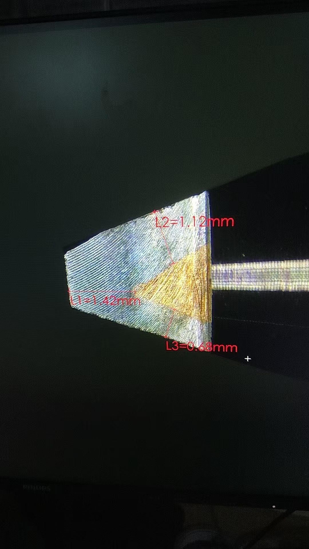
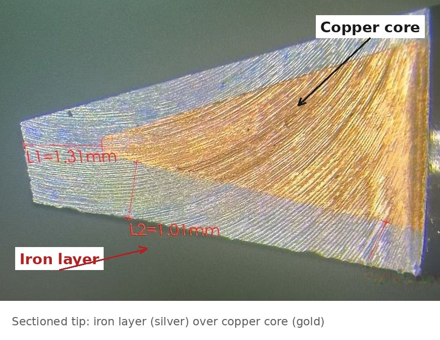
The iron plating layer protects the copper core from dissolving into molten solder, and it is the single biggest factor in tip lifespan. An automatic tip operates continuously — in some plants 24 hours a day, completing several joints per second — so it needs heavier plating than a hand-soldering station tip.
| Application | Recommended iron plating | Expected service life |
|---|---|---|
| Standard assembly, single shifts | 50–80 μm | Good |
| High-volume automated production | 80–120 μm | Extended |
| Lead-free and aggressive flux environments | 100–150 μm | Maximum |
Lead-free alloys (SAC305 and similar) melt roughly 30–40°C higher than tin-lead solder and attack iron plating faster, so a lead-free automatic line should specify thick, lead-free-compatible plating rather than reusing tips designed for tin-lead work. Automated plating lines with per-batch XRF thickness verification keep coating uniform from the first tip to the ten-thousandth. Full thickness selection logic is covered in our iron plating thickness guide for industrial soldering.
5. Calculate Cost Per Joint — Not Cost Per Tip
Unit price is the wrong metric for automated production. Consider the full equation:
Cost per joint = (tip price + line downtime cost) ÷ number of good joints produced
A budget tip lasting 5,000 cycles is not cheap when a precision tip lasts 50,000+. Every tip change on a robot means stopping the cell, swapping the consumable, and often re-checking the program position. On an inline system that stoppage propagates to the stations upstream and downstream.
The tip itself is a small fraction of soldering process cost — solder, flux, machine time and labor all dwarf it — but it has an outsized effect on yield. When lifespan, defect rate and downtime are counted together, quality automatic tips routinely cost less per joint than the cheapest catalog option. For the wider supplier-side evaluation, see how to choose a soldering tip supplier for automated production.
6. When a Standard Tip Is Not Enough
Catalog geometries cover most conventional joints, but automatic lines frequently run into situations no standard shape solves:
- Non-standard bend angles for boards with tall surrounding components
- Extended reach into deep fixtures or pallets
- Multiple grooves for unusual connector layouts
- Special contact surfaces for plated or difficult-to-wet materials
In these cases the tip should be developed from the application, not selected from a list. The standard workflow is: joint and interference analysis → custom geometry design → prototype within 2 weeks → line validation → mass production. Real examples include shaped automatic tips for a US communication equipment manufacturer, high-power bent tips for automotive electronics in Mexico, and a 480°C high-temperature custom solution for a Korean electronics plant.
Automatic Soldering Tip Selection Checklist
Before approving a tip for a production program, confirm every line below:
| Check item | What to confirm |
|---|---|
| Machine compatibility | Exact robot model, cartridge/holder type and current tip part number |
| Joint profile | Pad size, lead diameter, connector pin pitch and surrounding clearance |
| Geometry | PC / chisel / V-groove / bent selected for the actual joint |
| Thermal mass | Tip wets the joint in 2–3 s without raising temperature above 360°C |
| Iron plating | 80–120 μm for high volume; 100–150 μm for lead-free / aggressive flux |
| Material | 99.99% oxygen-free copper core, batch traceability available |
| Validation | Prototype run on the real machine with defect rate and recovery measured |
| Supply terms | MOQ, prototype lead time (≈2 weeks) and mass production lead time (3–4 weeks) |
Frequently Asked Questions
Can I use hand-soldering tips in a soldering robot?
Sometimes physically, rarely correctly. Hand tips are designed for operator compensation and intermittent use; robot tips need tighter dimensional tolerance, heavier iron plating for continuous cycles, and geometry optimized for a fixed approach angle. Using hand-station tips in an automatic line usually means short life and unstable joints.
What is the difference between DV1 and DV2 V-groove tips?
DV1 tips have a single V-groove for drag soldering one row of connector leads. DV2 tips have a double groove profile, used for double-row connectors or applications where throughput and solder volume control are more demanding. Match the groove to the connector layout rather than using the larger profile by default.
How long should an automatic soldering tip last?
There is no universal number — lifespan depends on temperature, alloy, flux and joint count. A well-matched, properly plated tip on a correctly run lead-free line can reach 50,000+ joints. Premature wear (under 5,000–10,000) almost always points to a mismatch in geometry, plating, temperature or maintenance rather than normal consumption.
Do lead-free processes require different tips?
Yes. Lead-free solders need higher working temperatures and dissolve iron plating faster. Specify thicker (100–150 μm), lead-free-compatible iron plating, keep temperatures in the 320–360°C range, and always tin the working surface before idle periods.
What information do I need to provide for a custom automatic tip?
Send the machine model, photos or a drawing of the joint, board clearance constraints, solder alloy and flux, working temperature, target cycle time, and — best of all — a used tip sample or CAD file. With a sample or DXF/STEP drawing, a working prototype can normally be delivered within 2 weeks.
Need Help Selecting Tips for Your Automatic Line?
Zhongzhen manufactures standard and custom automatic soldering tips for Apollo Seiko, UNIX, TSUTSUMI, 911-type robots and JBC automated units. Send us your joint sample, engineering drawing or machine model — our engineering team will recommend geometry and plating, and deliver a working prototype in 2 weeks.
- Free sample and application evaluation — no commitment
- Custom tips from physical samples or DXF/STEP drawings
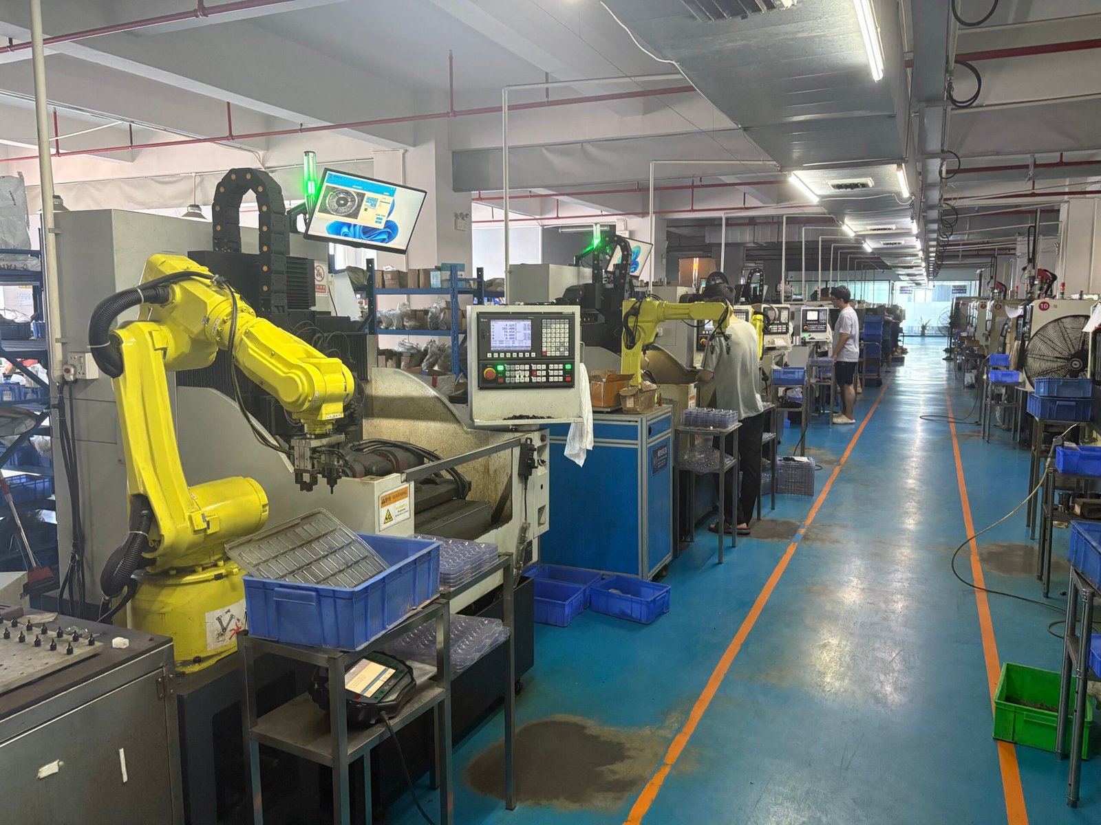
- 300,000+ pieces/month capacity with ±0.01 mm CNC precision
- XRF plating reports and full batch traceability