
Iron Plating Thickness Guide for Industrial Soldering Applications
If your automated soldering line is experiencing inconsistent tip life, poor wetting, or premature copper core exposure, the root cause may not be the tip design — it may be the iron plating thickness.
Iron plating is the single most critical factor in determining how long a soldering tip lasts. Yet most procurement teams and even some engineers don’t have a clear specification for what plating thickness they actually need.
After producing over 300,000 soldering tips per month for industries ranging from consumer electronics to automotive and communications equipment, we’ve developed a detailed understanding of how plating thickness affects performance. This guide breaks down everything you need to know.
Why Iron Plating Matters for Soldering Tips
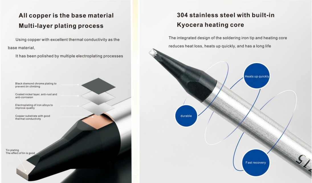
Soldering tips are made from oxygen-free copper (OFC) — an excellent conductor of heat but highly vulnerable to dissolution in molten solder. Without protection, the copper core would be eaten away within hours of contact with tin-based solder alloys.
The iron plating layer acts as a diffusion barrier between the copper core and the solder. It prevents the copper from dissolving into the solder bath while still allowing sufficient heat transfer for effective soldering.
Too thin, and the plating wears through quickly, exposing the copper to rapid erosion. Too thick, and thermal conductivity drops, causing cold joints and inconsistent soldering results.
Standard Iron Plating Thickness Ranges
Based on our manufacturing experience and customer feedback across different industries, here are the recommended plating thickness ranges for common applications:
| Application Type | Iron Plating Thickness | Typical Use Case | Expected Tip Life |
|---|---|---|---|
| Light-duty / Rework | 30–50 μm | Prototype work, low-volume rework stations | Short (hundreds of joints) |
| Standard Assembly | 50–80 μm | Through-hole and SMD assembly, moderate-volume production | Good (thousands of joints) |
| High-Volume Production | 80–120 μm | Continuous automated soldering, 8+ hour shifts | Extended (tens of thousands of joints) |
| Aggressive Flux / High Temp | 100–150 μm | Lead-free soldering (380°C+), aggressive rosin fluxes, automotive electronics | Maximum |
These ranges are not arbitrary — they represent the optimal balance between corrosion resistance (thicker plating) and thermal conductivity (thinner plating). The right choice depends on your specific process parameters.
What Happens When Plating Is Too Thin?
When iron plating is below the recommended thickness for your application, several problems emerge quickly:
- Rapid copper dissolution: The solder eats through the thin iron layer and begins dissolving the copper core. Within hours, the tip develops a hollow “crater” at the working surface.
- Poor wetting: As the iron degrades unevenly, solder no longer flows consistently across the tip surface, leading to cold joints and bridging defects.
- Frequent tip changes: Tips may need replacement every few hours instead of days or weeks, increasing both material cost and machine downtime.
- Inconsistent heat transfer: A corroded tip surface creates an air gap between the tip and the solder joint, reducing effective heat delivery.
In automated production, these problems compound quickly. A tip that fails on a high-speed placement machine can cause batch-level quality issues before the operator notices.
What Happens When Plating Is Too Thick?
Thicker plating is not always better. Excessive iron plating (above 150–200 μm) introduces its own set of problems:
- Reduced thermal conductivity: Iron conducts heat at only 80 W/m·K compared to copper’s 401 W/m·K. A thick iron layer creates a thermal bottleneck, slowing heat transfer to the solder joint.
- Cold solder joints: Insufficient heat delivery leads to incomplete wetting, especially on large thermal-mass joints like ground planes or heat sinks.
- Brittle plating layer: Very thick iron deposits tend to crack and spall under thermal cycling, creating rough surfaces that don’t hold solder well.
- Slower response time: In temperature-controlled stations, thick-plated tips respond more slowly to setpoint changes, reducing process stability.
This is why we recommend matching plating thickness to your specific application rather than defaulting to “maximum protection.”
How to Verify Iron Plating Thickness
If you’re sourcing soldering tips from a new supplier, you need a way to verify their plating specifications. Here are the two industry-standard methods:
1. XRF (X-Ray Fluorescence) Analysis
XRF is the most common non-destructive method for measuring plating thickness. An XRF analyzer directs X-rays at the tip surface and measures the fluorescent emission from each layer. The instrument then calculates the thickness of each coating based on emission intensity.
Advantages: Non-destructive, fast (seconds per measurement), can measure multiple points on the same tip for uniformity checking.
Requirements: The supplier must have an XRF analyzer (we use handheld units calibrated for Cu/Fe/Ni/Cr systems) and provide measurement reports with each batch.
2. Cross-Section Microscopy
For more detailed analysis, the tip is sectioned, polished, and examined under a metallurgical microscope. This reveals the actual plating structure — including layer boundaries, porosity, and adhesion quality.
Advantages: Provides visual confirmation of plating uniformity, layer bonding, and any internal defects.
Requirements: Destructive (consumes the sample), requires metallographic preparation equipment and trained technicians.
We recommend requesting both XRF data and cross-section images from your supplier during qualification. Ongoing production orders should include XRF reports for every batch.
How to Choose the Right Plating for Your Application
The optimal plating thickness depends on four factors:
- Solder alloy: Lead-free alloys (SAC305, Sn96.5/Ag3.0/Cu0.5) are more aggressive than Sn63/Pb37. For lead-free processes, aim for 80–120 μm minimum.
- Operating temperature: Higher temperatures accelerate iron dissolution. For continuous operation above 380°C, specify 100–150 μm.
- Flux chemistry: Highly active fluxes (high halide content, aggressive rosin formulations) erode plating faster. Match higher plating thickness to aggressive flux environments.
- Production volume: High-volume automated lines (8+ hours continuous operation) benefit from thicker plating (100–150 μm) to minimize changeover frequency. Low-volume or rework applications can use 50–80 μm for better thermal response.
When in doubt, request a sample set with different plating thicknesses and run a short trial to measure actual tip life in your process. This data-driven approach eliminates guesswork.
Quality Control: What to Expect from a Reliable Supplier
A professional soldering tip manufacturer should provide:
- Plating thickness specification for each tip model, matched to your application requirements
- XRF measurement reports included with every shipment, showing min/max/average thickness across sample tips
- Cross-section analysis available on request for qualification or failure investigation
- Batch traceability — every shipment traceable to production date, plating line, and material lot
At Zhongzhen, our automated plating lines maintain consistent 50–150 μm thickness with real-time monitoring. Every batch undergoes XRF verification before shipping. See our full manufacturing capability details for more information on our plating process.
Frequently Asked Questions
How often should I measure plating thickness on incoming tips?
For incoming quality control, we recommend XRF measurement on a statistical sample — typically 5 tips per 1,000 pieces or at least 3 per shipment. This catches plating variation without consuming time or resources on 100% inspection.
Can plating thickness vary within a single batch?
Yes, in poorly controlled processes. Manual plating operations can show ±20–30 μm variation within a batch. Automated plating with real-time monitoring should maintain ±5–10 μm consistency. Always ask your supplier about their plating process control method.
Does plating thickness affect solder wetting performance?
Indirectly, yes. Plating that is too thick reduces thermal conductivity, which can cause the tip surface to drop below optimal soldering temperature during contact. This manifests as poor wetting — the solder doesn’t flow smoothly. Properly specified plating thickness (matched to your temperature and alloy) should have no negative impact on wetting.
What is the cost difference between 80 μm and 150 μm plating?
Thicker plating requires more plating time and material, typically adding 10–25% to the base tip cost. However, the cost of tip failure in production (downtime, scrap, rework) usually far exceeds this material cost difference. For high-volume automated lines, thicker plating almost always delivers lower total cost of ownership.
Can you measure plating on our existing tips and recommend an improvement?
Yes. Send us a sample of your current tips along with your process parameters (solder alloy, temperature, flux, shift duration). We’ll perform XRF and cross-section analysis, then provide a recommendation for optimized plating thickness. See our guide to choosing a soldering tip supplier for more evaluation criteria.
Need Help Specifying Plating Thickness for Your Production?
If you’re experiencing tip life issues or want to optimize your soldering process, send us your tips and process parameters. Our engineering team will analyze your current setup and recommend the optimal plating specification.
- Free sample evaluation and plating analysis
- XRF and cross-section reports included
- Custom plating thickness available for any application
- 300,000+ pcs/month capacity with full batch traceability