
Why Soldering Tip Life Is Getting Shorter — Iron Layer, Heat, and Cost Per Joint
A purchasing manager put it plainly last year: “Five years ago a tip lasted three months. Now the same tip lasts four weeks and nobody changed anything.”
Something did change, and it is measurable. It is not the solder, and in most cases it is not the operator. It is the amount of iron between the copper core and the solder — the part of a soldering tip that does all the actual work, and the part that almost never appears on a quotation.
This article covers what the iron layer is, how it fails, how to measure it, and how to calculate what tip wear actually costs you per joint.
A Soldering Tip Is Not a Piece of Metal
A soldering tip is a layered structure, and each layer exists for one reason.
Copper core. Oxygen-free copper conducts heat extremely well. It is also almost completely unprotected against molten solder — solder dissolves copper at a rate that will destroy a bare copper tip in days.
Iron layer. A wall of pure iron, metallurgically bonded over the copper. Iron resists dissolution in solder far better than copper, and it is hard enough to survive contact with pads and components. This layer is the tip’s working life. When it is gone, the tip is gone.
Chrome or nickel passivation on the non-working surfaces. This exists purely so solder does not climb up the shaft.
The important point: the iron layer is not a thin electroplated coating measured in microns. On industrial tips it is a substantial iron wall — measured in millimetres, not micrometres. That distinction is where most of the confusion in this market starts.
If you write “plating thickness 1.2 mm” on an English-language datasheet, an experienced engineer will assume you mean 1.2 µm, decide the number is wrong, and stop reading. The correct term is iron layer thickness or iron wall thickness. The number is the same; the credibility is not.
How We Check the Iron Layer
You cannot judge iron layer thickness by looking at a tip, by its weight, or by how it feels. It requires cutting a tip open and measuring the cross-section under magnification.
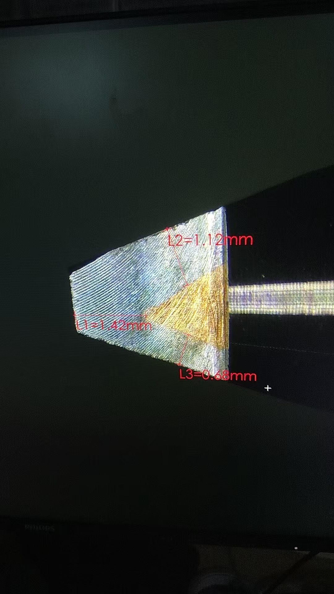
We do this on production samples. Two tips from different production runs, sectioned at the same magnification:
Figure 1 — Section A
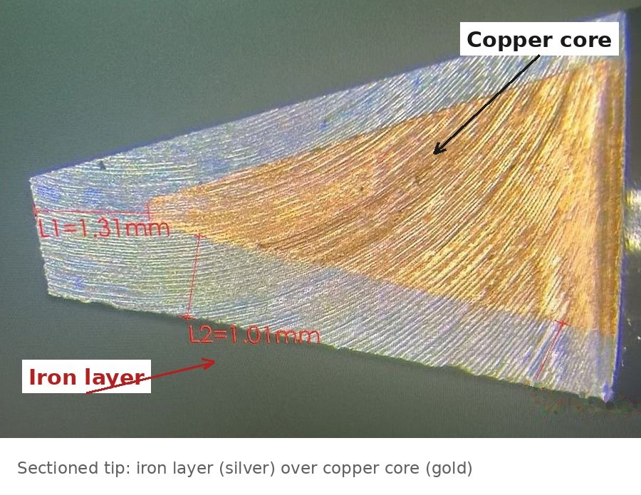
Figure 2 — Section B
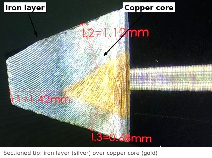
Read what is actually in these images. The silver material wrapping the gold core is iron. The gold is copper. The iron does not sit on the surface as a skin — it forms the entire working end of the tip, with the copper core running through the middle as a heat path.
Across production samples, iron layer thickness on the working face measures above 1.0 mm. The variation between the two samples reflects normal manufacturing tolerance, not a quality difference. What matters is whether that thickness stays within the specified range across batches — which is why every production lot is sectioned and measured rather than spot-checked by eye.
A note on the images: they were captured from the inspection monitor, so screen artifacts are from the capture, not from the samples. We keep the raw measurements on file.
What the specification looks like
For reference, our internal specifications on common geometries:
| Tip type | Working face | Each flank |
|---|---|---|
| 911G flat tip | 1.2 mm | 0.4 mm |
| D and DV types | 1.5 mm | 0.5 mm |
The asymmetry is deliberate. The working face takes the thermal and mechanical load — every joint, every contact, every heat cycle. The flanks see much less. Putting 1.2 mm where the work happens and 0.4 mm where it does not is not a cost saving; it is correct engineering.
How the Iron Layer Disappears
Iron does not oxidize away. It is removed by four mechanisms, and they run simultaneously.
1. Dissolution in solder
Molten solder dissolves iron, slowly but continuously. Every second the tip is wet with solder at temperature, a small amount of iron enters the solder. This is unavoidable — it is the price of the iron layer doing its job. The rate depends on temperature, alloy, and time.
At 350 °C the dissolution rate is manageable. At 400 °C it roughly doubles. This is why the single most effective tip-life intervention is turning the temperature down, and why “crank it up to be safe” is the most expensive habit in the workshop.
2. Mechanical wear
Contact with pads, leads, and components abrades the iron. So does cleaning — brass wool removes a tiny amount of iron every stroke, which is acceptable, but abrasive cloth and files remove a lot, which is not.
Automatic soldering machines are harder on tips than hand soldering, because the machine applies the same force thousands of times without an operator adjusting. Tips on automated lines typically need replacement on a joint-count basis, not a calendar basis.
3. Thermal cycling
Every heat-up and cool-down cycle puts stress on the bond between iron and copper, because the two metals expand at different rates. Repeated cycling eventually produces micro-cracks. Once cracked, solder reaches the copper through the crack and the failure accelerates.
Sleep mode and standby temperature reduce cycle count dramatically. A station that idles at 250 °C instead of cooling to room temperature and reheating has far fewer cycles per day.
4. Flux attack
Organic acid and water-soluble fluxes attack iron directly at temperature. Used correctly — applied, reflowed, cleaned immediately — the damage is manageable. Left on a hot tip between boards, it keeps eating.
Five Things That Shorten Tip Life (Ranked by Impact)
From production data across customer sites, roughly in order of how much life they cost:
1. Running 40–60 °C hotter than needed. Costs 30–50 % of tip life. Usually done “for safety” or because the station was set once and never revisited.
2. Idle time at working temperature. A tip sitting hot and dry between boards. Costs 20–40 %. Fix: sleep mode.
3. Not re-tinning after cleaning. A clean dry tip at temperature re-oxidizes within minutes, and the oxide layer then has to be removed again — each cycle removes iron. Costs 10–20 %.
4. Abrasive cleaning. Sandpaper, files, emery cloth. Directly removes iron. A tip cleaned this way daily can lose a third of its iron layer in a year.
5. Buying thin-iron tips. The most invisible one. A tip with 0.5 mm of iron instead of 1.2 mm does not fail faster because of anything the operator did — it simply has less material to lose. On a line running three shifts, that difference shows up as a 3× replacement frequency with no change in handling.
The Cost Calculation Nobody Runs
Tip price is the wrong number to optimize. What matters is cost per joint.
A worked example. Two tips, same geometry, same machine:
| Tip A (thick iron layer) | Tip B (thin iron layer) | |
|---|---|---|
| Price | $8.00 | $3.50 |
| Joints per tip | 60,000 | 18,000 |
| Replacement labour | $1.50 | $1.50 |
| Downtime per change | $4.00 | $4.00 |
| Rework from late-stage wear | 0.05 % of joints | 0.25 % of joints |
| Rework cost per joint | $0.40 | $0.40 |
| Cost per joint | $0.00024 | $0.00053 |
Tip B looks 56 % cheaper on the quotation and costs more than twice as much per joint.
The rework line is the one most calculations leave out, and it is usually the largest. A tip does not fail cleanly — it degrades. In the last 10–20 % of its life it produces marginal joints: insufficient wetting, cold joints, occasional bridging. Those joints leave the station looking fine and fail at functional test or in the field.
On a line producing 200,000 joints a month, the difference between these two tips is roughly $58 per month — about $700 a year, per station. On a line with 20 stations, that is $14,000, and it does not include the field failures.
What Actually Extends Tip Life
Ranked by return on effort:
- 1. Set the temperature to the joint, not to the maximum. Lead-free at 330–350 °C covers most work. Reserve 380 °C for heavy ground planes, and bring it back down afterwards.
- 2. Enable sleep mode. 250 °C after five minutes idle. This is the highest-return single change available.
- 3. Tin before shutdown and after every cleaning. The solder layer is the protection.
- 4. Brass wool only. No sandpaper, ever.
- 5. Match geometry to the joint. Right shape means shorter dwell, which means less dissolution.
- 6. Track joints per tip, not days per tip. If you do not know how many joints a tip produced, you cannot tell whether a change helped.
That last one is worth emphasising. Most factories measure tip life in weeks. Weeks are not a unit of wear — a station running 200 joints a day and a station running 3,000 joints a day will report completely different “tip life” for identical tips. Measure joints, and the numbers become comparable.
What to Ask a Supplier
If tip life is a real cost line for you, these are the questions that separate suppliers:
- What is the iron layer thickness on the working face, in mm? Not “high quality iron plating”. A number.
- How is it verified? Cross-section measurement, or a datasheet claim?
- Is it measured per lot? Ask to see a section image from a recent lot.
- What is the tolerance? A specification without a tolerance is not a specification.
- What is the copper core grade? Oxygen-free copper or standard electrolytic copper.
A supplier who can answer the first three with numbers and images is doing real inspection. A supplier who answers with adjectives is not.
Related reading: Iron plating thickness guide for industrial soldering · Iron-plated soldering tips · Compatible vs. original soldering tips · Soldering tips for automatic soldering machines